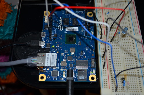
As part of my latest project, I’ve been trying to come to terms with how the GPIO’s (General Purpose Input / Output) on the Galileo work, there are several ways to program the Galileo I/O’s, mainly: GPO, SPI or ADC.
As the Galileo is running Linux and emulating the Arduino IDE, the GPIO’s run a lot slower than expected, as the chip copes with this overhead.
The GPIO’s on the Galileo are routed through the Cypress CY8C9540A chip, which drastically slows down the performance of these pins, however, not all of the GPIO pins are routed through the PWM.
While reading up on this, I found the below post by “deckard026354” on the Intel communities site, which states the Galileo has 2 dedicated IO’s with “significant data rates”.
I managed to get my hands on a Saleae Logic Analyser, which I used to measure the speeds of the GPIO.
I created a basic sketch on the Arduino IDE and measured the frequency at the Galileo outputs.
Default speed – 226Hz:
int led = 2;

void setup() {
  pinMode(led, OUTPUT);
}

void loop() {
  digitalWrite(led, HIGH);
  digitalWrite(led, LOW);
}
Output:
As expected, the wave form reads 226Hz, pretty slow though – so lets see what we can do about that.
Example-1 – outputs 477kHz waveform on IO2:
void setup() {
  // put your setup code here, to run once:
  pinMode(2, OUTPUT_FAST);
}

void loop() {
  // put your main code here, to run repeatedly:
  digitalWrite(2, HIGH);
  digitalWrite(2, LOW);
}
Output:
The output measures 444KHz, not too shabby. Although I seem to me missing 33Hz… I’ve measured this a few times and am pretty sure it’s accurate. So it could possibly be down to the overhead from the Galileo emulating the Arduino IDE.
Example-2 – outputs 683kHz waveform on IO3:
void setup(){
    pinMode(2, OUTPUT_FAST);
}

void loop()
{
    register int x = 0;
    while(1){
        fastGpioDigitalWrite(GPIO_FAST_IO2, x);
        x =!x;
    }

}
Output – 705KHz:
The pulses generated seemed to alternate between 667KHz and 705KHz, I’m not sure if this is an inaccuracy with the Galileo or the Saleae, although this does average at 686KHz, so it looks to be an issue with the measurement.
Example-3 – outputs 2.93MHz waveform on IO3:
uint32_t latchValue;

void setup(){
    pinMode(3, OUTPUT_FAST);
    latchValue = fastGpioDigitalLatch();
}

void loop()
{
    while(1){
        fastGpioDigitalWriteDestructive(latchValue);
       latchValue ^= GPIO_FAST_IO3;
    }

}
Output:
Nice! 3MHz from a GPIO,
Although I’m a bit worried about the function name “fastGpioDigitalWriteDestructive“, so I’d like to know a bit more about this before using it in a dedicated sketch.
Example-4 – outputs 2.93MHz waveform on both IO2 and IO3:
uint32_t latchValue;

void setup(){
    pinMode(2, OUTPUT_FAST);
    pinMode(3, OUTPUT_FAST);
    latchValue = fastGpioDigitalLatch(); // latch initial state
}

void loop()
{
    while(1){
        fastGpioDigitalWriteDestructive(latchValue);
        if(latchValue & GPIO_FAST_IO3){
            latchValue |= GPIO_FAST_IO2;
            latchValue &= ~ GPIO_FAST_IO3;
        }else{
            latchValue |= GPIO_FAST_IO3;
            latchValue &= GPIO_FAST_IO2;
        }
    }
}
Output:
I didn’t get this to work -_-
If I get a chance, I’ll go through the code again at a later stage and debug…
So there you go, depending on how you program IO2 or IO3, you can get:
- 226Hz by using the default setup.
- 477KHz by using pinMode(2, OUTPUT_FAST).
- 683KHz by using fastGpioDigitalWrite(GPIO_FAST_IO3, x);
- 2.93MHz by using fastGpioDigitalWriteDestructive – although I don’t like the sound of this command…


