Introduction:
I started this project as a bit fun, when I first bought my Galileo board. As this was my first Arduino project, I decided to try downloading an already completed project and get it working on my own board. I soon realised this wouldn’t be as easy as I thought…
As the Intel Galileo is actually a Linux computer emulating the Arduino IDE, the GPIO speeds are a lot slower on the Galileo when compared to a dedicated microcontroller. This proved to be a big problem for me, as it meant I couldn’t just run any of the timing or frequency dependant Arduino projects directly on the Galileo.
With this in mind, I decided to build the Infra-Red remote control for my Nikon SLR camera. As the Arduino libraries would not work for the Galileo, I decided to build my own.
How the command signal works:
The command signal is transmitted on a 38.4KHz carrier wave, the command signal is sent in a binary format.
This means, when sending a binary “1”, the LED is turned on and off at a frequency of 38400 times a second for a given time period of 400uS. When transmitting a “0”, the LED remains off for 400uS.
Luckily for me the command signal for the Nikon camera has already been decoded and published, the details can be found here: http://www.sbprojects.com/projects/nikon/
So, from observing the diagram on the SB Projects page, we can convert each binary value of the command signal into a series of pulses generated on the carrier frequency. The pulses can be turned on or off to generate the binary values.

Creating a binary “1” and piecing together the command signal.
Parts list:
- Intel Galileo.
- IR LED – I broke open an old remote control and took the LED from here.
- Resistor – 220Ω.
- Breadboard – for building a prototype design.
- Nikon Camera – you know, to use the remote control on…
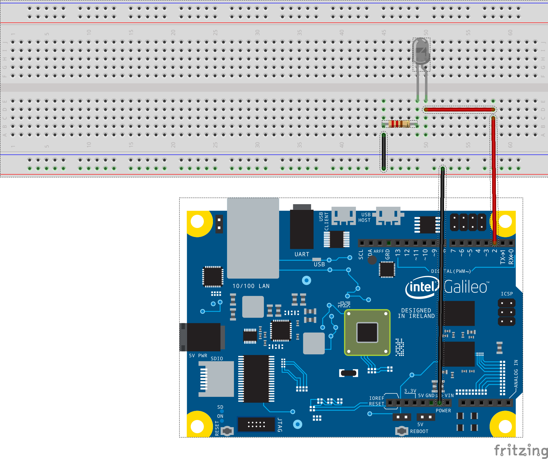
Schematic:

Schematic diagram for the circuit.
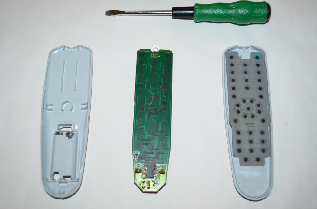
Salvaging an IR LED from an old remote:
I had been looking to buy an IR LED but as they’re so cheap, I couldn’t find anywhere that would ship one to me unless I bought about €40 worth of items, so my dad donated his old TV remote, which I broke open and removed the IR LED.
Time to open it up and remove the LED:
Work in progress.
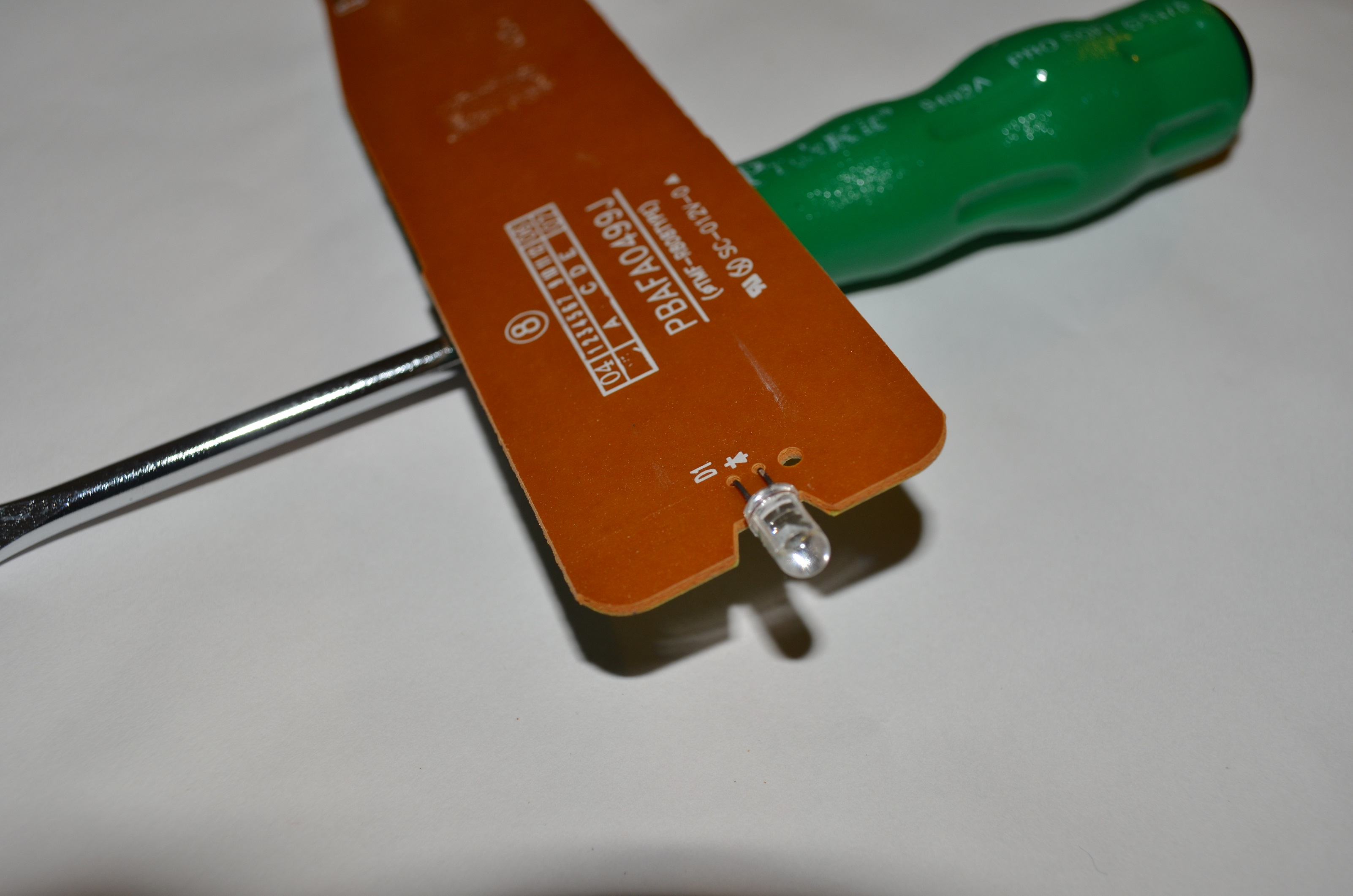
I used a wire snips to cut off the IR LED:

Here’s a close up of the IR LED, just in case you’ve read this far and still don’t know what I’m taking about (highly possible).
Creating the 38.4KHz clock pulses:
In order to generate the command pulse, we need to be able to create a clock frequency of 38.4KHz and turn this off and on to create the binary values. I’ve already created a post on how to create a clock pulse using the Galileo, you can view it here.
For this project I am using the method shown in example 1, which is plenty fast for what we need.
The code from example 1 outputs a 444KHz frequency (I’ve measured this as 444KHz, it should be 477KHz, which is why some of the maths may not add up), which is way too fast, so we’ll need to add in a delay to slow that down, in this case the delay is created with an “for statement”. We use a delay value of 12 as this translates to 38.4KHz, so in order to generate the required frequency – we turn on the LED and count for 12 clock periods, then turn off the LED and count for another 12 clock periods.
void pulseLoop(int pulses, int SHINE)
{
  // Integers for loops:
  int i;
  int n;
  // delayValue is used to delay the clock from 460KHz to 38.4KHz:
  int delayValue = 12;

  register int x = 0;

  // Loop to control the number of pulses created
  // Number is multiplied by 2 to create both the low and high period of the pulse:
  for(n=0; n<(pulses*2); n++)
  {
    // Loop to delay the digitalWrite to 38.4KHz:
    for(i=0; i<delayValue; i++)
      {
        // SHINE only activated the IR LED when we are supposed to pulse, deactivates for the delay:
        digitalWrite(2, (x & SHINE));
      }
    x =!x;
 }
}
Here’s how that code looks on a Logic Analyser:
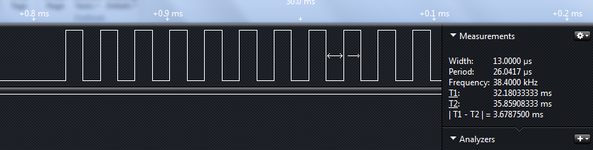
38.4KHz clock frequency created using the GPIO example 1.
Using the code above, we can call the function pulseLoop and pass the number of required pulses and the LED state as an argument, for example we could just type in:
  // First Pulse:
  pulseLoop(76, 1);
  pulseLoop(1058, 0);
  pulseLoop(15, 1);
  pulseLoop(61, 0);
  pulseLoop(15, 1);
  pulseLoop(137, 0);
  pulseLoop(15, 1);
  // Wait for 2nd pulse
  pulseLoop(1078, 0);
  // Second Pulse:
  pulseLoop(76, 1);
  pulseLoop(1058, 0);
  pulseLoop(15, 1);
  pulseLoop(61, 0);
  pulseLoop(15, 1);
  pulseLoop(137, 0);
  pulseLoop(15, 1);
Creating the full command:
The code above works – however it’s a bit too messy and just not cool really..
So lets put all of our pulse values into an array and create a new function which will use that array to build the command.
// Create an array for the pulse values:
int nikonCommand[16] = {76, 1058, 15, 61, 15, 137, 15, 1078, 76, 1058, 15, 61, 15, 137, 15, 1078};

void takePicNikon()
{
for(int x=0; x<sizeof(nikonCommand)/sizeof(int); x++)
  {
    int y = x + 1;
      pulseLoop(nikonCommand[x], (y%2));
  }
}
The line “pulseLoop(nikonCommand[x], (y%2));” uses the C language modulus operator to tells us if the index number is even, if it is we pass a “1” into the pulseLoop function, this will switch on the LED for each item in the array.
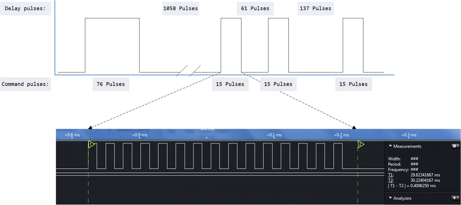
Full command:
Using the above code, it was possible to replicate the command required for the Nikon camera, here is a
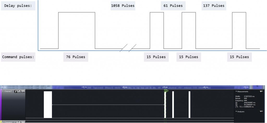
The full command pulse, with the Logic Analyser data.
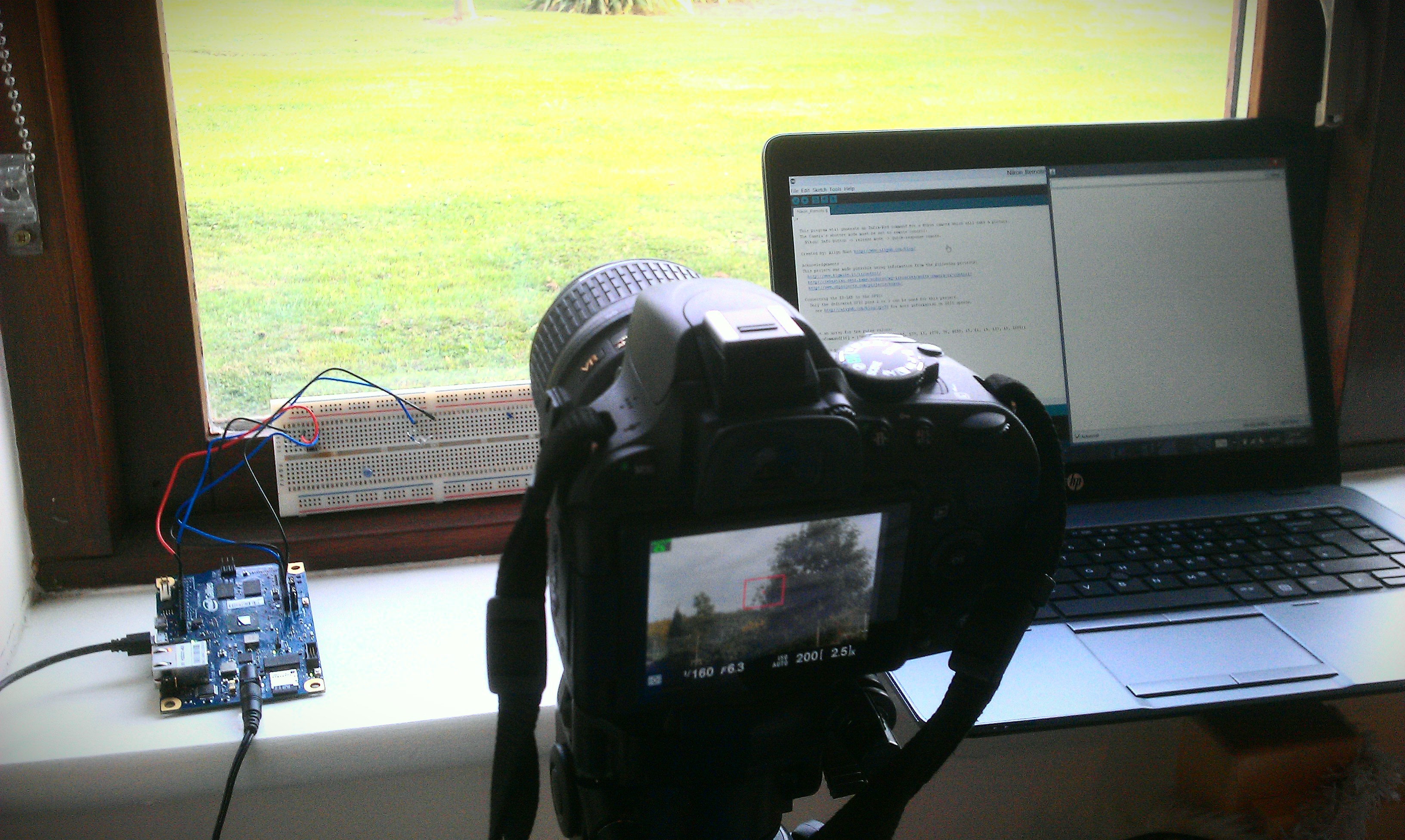
It’s Working!!!
This is also Horstachio’s big screen debut…
Galileo – IR Remote for Nikon Camera.. from Allyn H on Vimeo.
Grab the code here:
Feel free to use my code, make something yourself. It should be very easy to port this to any other make camera.
Please let me know if you plan on using this in any projects 🙂
Link to my code on GitHub.