Twitter have developed an API (Application Programming Interface) for their website, which makes it really easy to send and receive Tweets from your Raspberry Pi or Galileo! The Twitter API takes all of the hard work out of writing a program to interface with Twitter, There are several ways to access the Twitter API, the easiest of which (in my opinion anyway 🙂 is to use the Twython package of the Python language.
Differences between Raspberry Pi and the Galileo:
It’s really easy to install Twython on the Raspberry Pi, a little harder to install on the Galileo – so for that reason, I’ll show the step-by-step instructions from the Galileo install. The only difference is the Galileo doesn’t require you to use the sudo command as you already have root permissions set. For example, when editing a file with the Galileo you would use:
# nano my_file.txt
When editing the file on a Raspberry Pi you would use:
# sudo nano my_file.txt
Changing the date on the Galileo:
In order to install some of these packages, you’ll need to update the date and time of your Galileo – this isn’t automatically done when you connect to the internet as you may expect. If you don’t update your date and time, you’ll get SSL certification errors when you try to download the Twython package.
To change the date and time – use the following command in the format year-month-day hour:minute:second:
# date --set="2015-01-20 10:00:00"
Installing Twython (and other Python packages):
In order to connect our computer to Twitter, we’ll need to download some Python packages:
- setuptools – this will allow you to “Easily download, build, install, upgrade, and uninstall Python packages.”
- pip – this is a Python package installer.
- twython – this is the package which will actually interface with Twitter.
Here are the commands to install these packages – remember if you’re on a Raspberry Pi you’ll need to put “sudo” in front of each command.
# apt-get install python-setuptools
Here’s what that looks like on your computer, when asked “do you want to continue” as per the picture below – enter “y”. to continue.
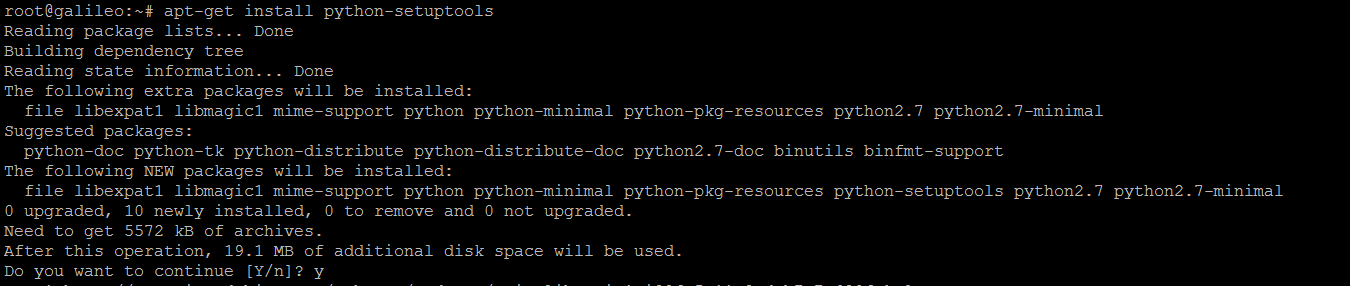
Installing the setuptools Python package.
Next, install the “pip” package:
# easy_install pip
Finally, using pip – install the Twython package:
# pip install twython
Creating a Twitter App:
To create a Twitter App, you’ll need to sign up to Twitter and register the account as an application. This is important as you’ll need to verify this App with Twitter every time you use it. The verification method Twitter uses is called OAuth 2.0 to verify your App, this means you’ll never have to supply your password to 3rd party App developers but it does make it a little harder to verify your App – the good news is, Twython and other API’s handle all the OAuth pain, all you need to do is register your App and save the information. Register your app here: https://apps.twitter.com/ Click on “Create New App” and enter your information.
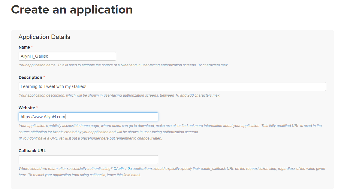
Creating an App.
Changing App permissions:
As this is your App and you’ll want to be able to play around with it – you can chance the App permissions to allow you to read, write and access your direct messages. You can change these permissions at a later stage.
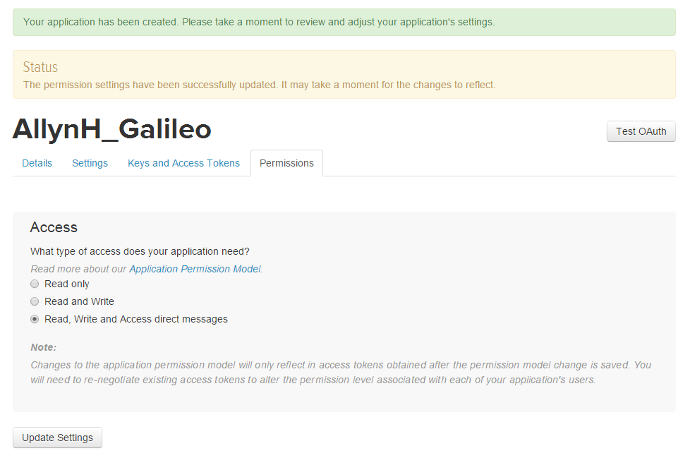
Change permissions.
Authorize your account:
You need to create your access token and access token secret before you use your App. Click on the “Keys and access tokens” tab. Click on the “Create my access token” button.
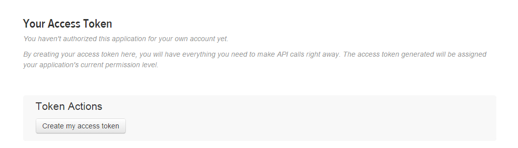
Generate your secret token.
You should now have all 4 pieces of required information:
- Consumer Key (API key).
- Consumer Secret (API Secret).
- Access Token
- Access Token Secret.
Now it’s time to write some Python!
Writing the Python:
Creating a Python file:
On your Raspberry Pi or Galileo, create a file called “Tweet.py” using the following command:
# nano Tweet.py
Now paste in the Python code:
Twitter Authorization:
In order to send a Tweet, you’ll need to send Twitter your OAuth information. This process is handled by the Twython package. Here we are creating 4 string objects and a Twython object called “twitter”. When we create the Twython object we are passing the 4 strings to it an arguments. These are the access keys you generated in the previous section.
CONSUMER_KEY = '<YOUR CONSUMER_KEY>'
CONSUMER_SECRET = '<YOUR CONSUMER_SECRET>'
ACCESS_KEY = '<YOUR ACCESS_KEY>'
ACCESS_SECRET = '<YOUR ACCESS_SECRET>'
twitter = Twython(CONSUMER_KEY,CONSUMER_SECRET,ACCESS_KEY,ACCESS_SECRET)
Reading in a command line argument:
To make the code a bit more flexible, we can pass the text we want to Tweet into the Python script as a command line argument. This is done by using the system “argv” parameter. In our case – we only want to take the first 140 characters of this text, as this is the character limit set by Twitter for each Tweet. We do that by using the command:
sys.argv[1][:140]
Executing the code:
You can execute the code from the command line like so:
# python Tweet.py "Hello world."
Here’s what that looks like on the Galileo:

Hello World!
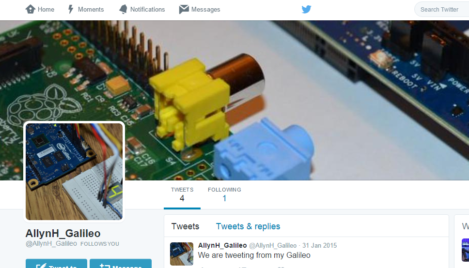
Then check your Twitter Bot!
Hello world.
— AllynH_Galileo (@AllynH_Galileo) January 18, 2015