Making things, writing code, wasting time...

Category: Galileo

Creating a Python app for Destiny – Part 4: Transferring and equipping items.

Introduction:

In the previous sections I showed how to:

  1. Send a request to read Xurs inventory.
  2. Send a HTML formatted email with Xurs inventory.
  3. Log into Destiny and Bungie.net via your PSN account.

I’m now going to build on the previously created code to create an app that can transfer an item to and from the vault, once the item has been transferred – we can then equip it.

If you’ve been reading along with me up to this point, you should understand all of this, if not – now is a good time to check out my previous posts.

Here’s the code working (sorry about the camera shaking, it was made using my phone ):

Destiny the game, Equipping an Item with the Destiny API. from Allyn H on Vimeo.

Also, I like to say a big thanks to all of the people on Reddit, Twitter and Bungie.net for their help and interest 🙂

You can find me on Twitter here @Allyn_H_

The transferItem endpoint:

The Destiny API uses web server endpoints to execute commands, the endpoint used to transfer items is: https://www.bungie.net/platform/Destiny/transferItem/

The BungieNetPlatform wiki for this endpoint can be found here. We can see this method is very different from the Xur advisors endpoint we used in the previous examples.

Here are the main differences:

  • We still need to use the X-API key in our header.
  • We also have to attach our x-csrf token in our header.
  • This is a private endpoint – we need to be logged in to use this method.
    • We need to attach the required cookies to our POST request.
  • This is a POST method – we will need to send data with this request.
    • We need to send the data as a JSON packet.
  • The response will only tell us if we have been successful or not – the Xur advisors response was >1000 lines of text.

The code for storing the transferItem endpoint variable will look like this:

base_url = "https://www.bungie.net/platform/Destiny/"
req_string = base_url + "TransferItem/"

Important note: If the trailing “/” is missing from the “transferItem/” endpoint – the request will fail. I’ve spent way longer than I’m willing to admit debugging that issue :/

Creating the POST request payload:

The “transferItem” endpoint takes a JSON payload as an input. This JSON payload contains a lot of information. So lets take a look at how it’s put together.

The data gathered to populate this payload was found by looking at items I had equipped using the “GetCharacterInventory” endpoint, you can find more info here. This will list the relevant information for all of your equipped items, let me know if you want to see the code for this.

Name

Description

membershipType

This will be 2 for PSN and 1 for Xbox live.

itemReferenceHash

This is the “itemHash” number from our previous examples. This refers to the generic item for example: 1000-Yard Stare.

itemId

This is a unique item number relating to a specific item, that you own. For example: Allyn’s 385 light level 1000-Yard Stare with the Ambush Scope, Quickdraw and Firefly.

stackSize

How many items to transfer. Should be “1” for equipable items.

characterId

The characterId the item is being moved to or from. You can find the characterId here.

transferToVault

Move the item to or from the vault; true or false

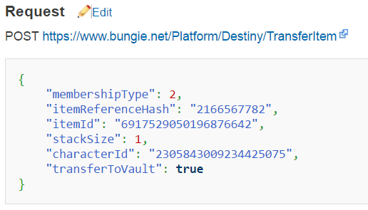
Here’s how this method expects the JSON data to be formatted:

This is the BungieNetPlatform example for the transferItem POST payload

This is the BungieNetPlatform example for the transferItem POST payload

The good news here is it’s pretty easy to put this together in Python by creating a Dictionary object.

Making a POST request:

We’ve already looked at making HTTP GET requests with Python, but the Python Requests library also makes it really easy to make a POST request.

You can view the Requests documentation here. Here’s the quick example of how to send some data formatted as a Python dictionary:

Python Requests POST example

Python Requests POST example

Or the Requests library will also automatically encode a Python dict into a JSON object for you, when you use the “json” parameter:

Python Requests POST JSON example

Python Requests POST JSON example

Now that we know how to create a Python POST request and what data the transferItem endpoint are looking for, lets turn that into some code!

Moving an item from your vault to your inventory:

As mentioned above – the data gathered to populate this payload was found by looking at items I had equipped by using the “GetCharacterInventory” endpoint, you can find more info here. I’m planning on putting together a blog post on this too but let me know if you’d like to see the code for this.

First we create our Python dictionary object:

text_payload = {
    "membershipType": 2,
    "itemReferenceHash": 1519376148, # The Ram
    "itemId": 6917529085991104887, # The Ram
    "characterId": characterId_Warlock,
    "stackSize": 1,
    "transferToVault": False
}

Next, we convert the dictionary object into a JSON object:

payload = json.dumps(text_payload)

Now we can make the actual POST request to the Destiny servers to transfer our item.

base_url = "https://www.bungie.net/platform/Destiny/"
req_string = base_url + "TransferItem/"
res = session.post(req_string, data=payload)

The JSON response should look like this:

{
    "ThrottleSeconds": 0, 
    "ErrorCode": 1, 
    "ErrorStatus": "Success", 
    "Message": "Ok", 
    "Response": 0, 
    "MessageData": {}
}

If the item was not found in your vault, you’ll get a response like this:

{
    "ThrottleSeconds": 0, 
    "ErrorCode": 1623, 
    "ErrorStatus": "DestinyItemNotFound", 
    "Message": "The item requested was not found.", 
    "Response": 0, 
    "MessageData": {}
}

For any other issues, for example if you were to omit the trailing “/” from “https://www.bungie.net/platform/Destiny/TransferItem/” URL, the request would fail but you wouldn’t receive a JSON response, instead your code would error and you’d receive a HTTP 405 status code. You can find the status code by using the following code:

print res.status_code
405

If you see something like that coming up, you’ll need to review and fix your code.

Equipping an item from your inventory:

Now that the item is in our characters inventory – we can equip the item on that character.

The endpoint used to equip an item from your inventory is: https://www.bungie.net/platform/Destiny/EquipItem/ you can find more information about this endpoint here.

Just a note: this can only be done when in a social space or in orbit (otherwise it’d be really easy to cheat in PvP – can you imagine if you could do this in Trials???). Otherwise the action will fail and return an error message.

Creating the POST request payload:

The POST request to equip an item is smaller and we already have the details of the item we want to equip.

text_equip_payload = {
    "membershipType": 2,
    "itemId": 6917529085991104887, # The Ram
    "characterId": characterId_Warlock
}
equip_payload = json.dumps(text_equip_payload)


equip_url = base_url + "EquipItem/"
res = session.post(equip_url, data=equip_payload)

Again, if the item was not found, you’ll get a response like this:

{
    "ThrottleSeconds": 0, 
    "ErrorCode": 1623, 
    "ErrorStatus": "DestinyItemNotFound", 
    "Message": "The item requested was not found.", 
    "Response": 0, 
    "MessageData": {}
}

If you’re trying to equip an exotic and you already have one equipped, you’ll see an error message like this:

{
    "ThrottleSeconds": 0, 
    "ErrorCode": 1641, 
    "ErrorStatus": "DestinyItemUniqueEquipRestricted", 
    "Message": "You can only have one item of this type equipped.", 
    "Response": 0, 
    "MessageData": {}
}

Running the code:

Here is the full set of Python code, this can be copied into a file called “equipItem.py” and executed from the command prompt like so:

> python equipItem.py

The code can also be found on my GitHub page here: https://github.com/AllynH/Destiny_Equip_Item

As always, I’ll try to keep the GitHub repo up to date with any changes I make.

Creating a Python app for Destiny – Part 2: Emailing Xurs inventory.

Introduction:

In the previous tutorial, I showed how you could use Python to send a request using the Destiny API, to the Bungie servers and how to decrypt the JSON reply. If you haven’t read the previous tutorial, it’s right here. I’m going to gloss over how to write the HTML, as there are plenty of really good online resources for creating and styling websites, checkout codecademy if you’re interested in a free guide.

In this tutorial I will continue on with the program we have created, to:

  1. Change our Get_Xur_inventory.py program so it writes the output as a HTML file.
  2. Have the program send this HTML, via Gmail, directly to our  email.

By writing our output as HTML we have a lot more control over the design and formatting of the email. Using HTML will also allow us to directly embed the item pictures into out email, from the URL links provided in the JSON response from Xur.

The hard part of the code is already done, with a few minor tweaks, we can have our program output Xurs inventory into a HTML formatted email.


Outputting Xurs inventory as HTML:

In order to create our output HTML, we are going to use a template HTML file to store as much of the generic HTML as possible, and change all of the print statements in our code to output HTML formatted data.

HTML file structure is split into 3 main parts, such as HTML version information, <head>, and <body> tags. We are going to take advantage of that and save the HTML version information and <head> section in a template HTML file, which we can reuse every time we run the script. This would allow us to update any of the generic HTML code separately – for example if you wanted to change some styling or CSS information, without messing with your Python code

We can then use our script to generate only the HTML needed to display the items from Xurs inventory, this will change every week so needs to be generated every time we run our script.

Opening our template HTML file:

The following code will open a file called “template.html” for reading, and save all of the contents into a string object called “my_html”, then close the file.

template_file = open('template.html', "r")
my_html = template_file.read() template_file.close()

Outputting HTML from our Python code:

Below is an example of how we’d like to format the HTML code, essentially we wrap it in a couple of <div>’s and display the image and text.

<div class="col-md-4">
 <div class="thumbnail">
 <a href="item_url">
 <img src="item_url">
 </a>
 <h3>Item name: item_name</h3>
 <p>Item type is: item_type<p>
 <p>Description: item_description<p>
 </div>
</div>

Here’s what the corresponding Python code looks like:

my_html = my_html + "<div class=\"col-md-4\">\n"
my_html = my_html + "\t<div class=\"thumbnail\">\n"
my_html = my_html + "\t\t<a href=\"" + item_url + "\">\n"
my_html = my_html + "\t\t<img src=\"" + item_url + "\">\n"
my_html = my_html + "\t\t</a>\n"
my_html = my_html + "\t\t<h3>" + item_name + "</h3>\n"
my_html = my_html + "\t\t<p>" + item_type + "<p>\n"
my_html = my_html + "\t\t<p>" + item_description + "<p>\n"
my_html = my_html + "\t</div>\n"
my_html = my_html + "</div>\n"

We’ve wrapped each of the lines of HTML code in a write statement. We’ve already populated all of the item_url, item_name, item_type and item_description variables with our code.

So here’s what each line is doing. In this example we are creating a <h3> heading, with the text from our “item_name”. “\t” creates a tab and “\n” moves to a new line. All of this text is concatenated into one string, which we add on to the end of the “my_html” string object.

my_html = my_html + "\t\t<h3>" + item_name + "</h3>\n"

Closing the HTML:

Now that we have created and populated <div>’s with each of Xurs items, we can add the code to close the HTML </body> and </html> tags.

my_html = my_html + "\t\t</div> <!-- row -->\n"
my_html = my_html + "\t</div> <!-- container -->\n"
my_html = my_html + "</div> <!-- inventory-container -->\n"
my_html = my_html + "</body>\n"
my_html = my_html + "</html>\n"

The “my_html” string will store all of the HTML code used in the body of the email we send.

Sending an email with Python:

Python comes installed with a number of really useful libraries, including the smtplib (Simple Mail Transfer Protocol library) and the MIMEMultipart and MIMEText (Multipurpose Internet Mail Extensions, allows text, images and other options) libraries.

For this section I referenced two tutorials, here Nael Shaib shows how to make a basic email program, and here Darren Massena shows how to create a HTML formatted email and attach external pictures.

Some important notes:

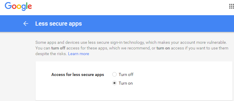
Google recently changed their security requirements, so to use this program, you will need to change your Google settings to allow less secure apps. I needed to do the following:

  1. Click here to allow less secure apps. Google will still reject access to your account, until you authorise it.
  2. Click here to authorise your app. This will authorise your app access to your Google account.
  3. Gmail and some other mail clients do not support CSS styling, so if you wanted to convert some existing CSS to inline HTML, you could use a tool like this. That being said, my iPad and Android phone both display mails with full CSS – so I’ve included some CSS styling in my code 🙂
Enable access for less secure apps.

Enable access for less secure apps.

Alright, that’s enough talk – lets get to coding!

Importing the required libraries:

First lets import the required libraries:

import smtplib
from email.MIMEMultipart import MIMEMultipart
from email.MIMEText import MIMEText

Next we’ll set up our email address parameters, enter your details as follows.

# Mail parameters:
fromaddr = "TO_ADDRESS"
toaddr = "FROM_ADDRESS"
password = "GMAIL_PASSWORD"

Next, lets create the email header information:

# Compose mail: 
msgRoot = MIMEMultipart() 
msgRoot['From'] = fromaddr 
msgRoot['To'] = toaddr 
msgRoot['Subject'] = "Xurs Inventory." 
msgRoot.preamble = "This is a multipart message in MIME format." 

The line:

msgRoot = MIMEMultipart()

creates an email MIMEMultipart object, we then set the [‘To’], [‘From’] and [‘Subject’] parameters of the email on the following 3 lines.

Creating the email body:

We’ve already populated the HTML into a string object called “my_html”.

The “my_html” string object is added to the body of the email with the following commands, the 2nd parameter  passed to the MIMEText object sets the email type as HTML:

msgText = MIMEText(my_html, 'html')
msgAlternative.attach(msgText)

The following commands create an SMTP mail object, connect to the Gmail SMTP server on port 587.

server = smtplib.SMTP('smtp.gmail.com', 587)
server.ehlo()
server.starttls()

The next line actually logs into our Gmail account, we pass our Gmail address and password as parameters to this.

server.login(fromaddr, password)

The next 2 lines actually send the email,

server.sendmail(fromaddr, toaddr, msgRoot.as_string())
server.quit()

Running the code:

Here is the full set of Python code, this can be copied into a file called “Get_Xur_inventory_email.py” and executed from the command prompt like so:

> python Get_Xur_inventory_email.py

The code can also be found on my GitHub page here: https://github.com/AllynH/Destiny_Get_Xur_inventory_email

As always, I’ll try to keep the GitHub repo up to date with any changes I make.
Making a Twitter-Bot on your Galileo or Raspberry Pi

Twitter have developed an API (Application Programming Interface) for their website, which makes it really easy to send and receive Tweets from your Raspberry Pi or Galileo! The Twitter API takes all of the hard work out of writing a program to interface with Twitter, There are several ways to access the Twitter API, the easiest of which (in my opinion anyway 🙂 is to use the Twython package of the Python language.

Differences between Raspberry Pi and the Galileo:

It’s really easy to install Twython on the Raspberry Pi, a little harder to install on the Galileo – so for that reason, I’ll show the step-by-step instructions from the Galileo install. The only difference is the Galileo doesn’t require you to use the sudo command as you already have root permissions set. For example, when editing a file with the Galileo you would use:

# nano my_file.txt

When editing the file on a Raspberry Pi you would use:

# sudo nano my_file.txt

Changing the date on the Galileo:

In order to install some of these packages, you’ll need to update the date and time of your Galileo – this isn’t automatically done when you connect to the internet as you may expect. If you don’t update your date and time, you’ll get SSL certification errors when you try to download the Twython package.

To change the date and time – use the following command in the format year-month-day hour:minute:second:

# date --set="2015-01-20 10:00:00"

Installing Twython (and other Python packages):

In order to connect our computer to Twitter, we’ll need to download some Python packages:

  1. setuptools – this will allow you to “Easily download, build, install, upgrade, and uninstall Python packages.”
  2. pip – this is a  Python package installer.
  3. twython – this is the package which will actually interface with Twitter.

Here are the commands to install these packages – remember if you’re on a Raspberry Pi you’ll need to put “sudo” in front of each command.

# apt-get install python-setuptools

Here’s what that looks like on your computer, when asked “do you want to continue” as per the picture below – enter “y”. to continue.

Package 1 of 3.

Installing the setuptools Python package.

Next, install the “pip” package:

# easy_install pip

Finally, using pip – install the Twython package:

# pip install twython


Creating a Twitter App:

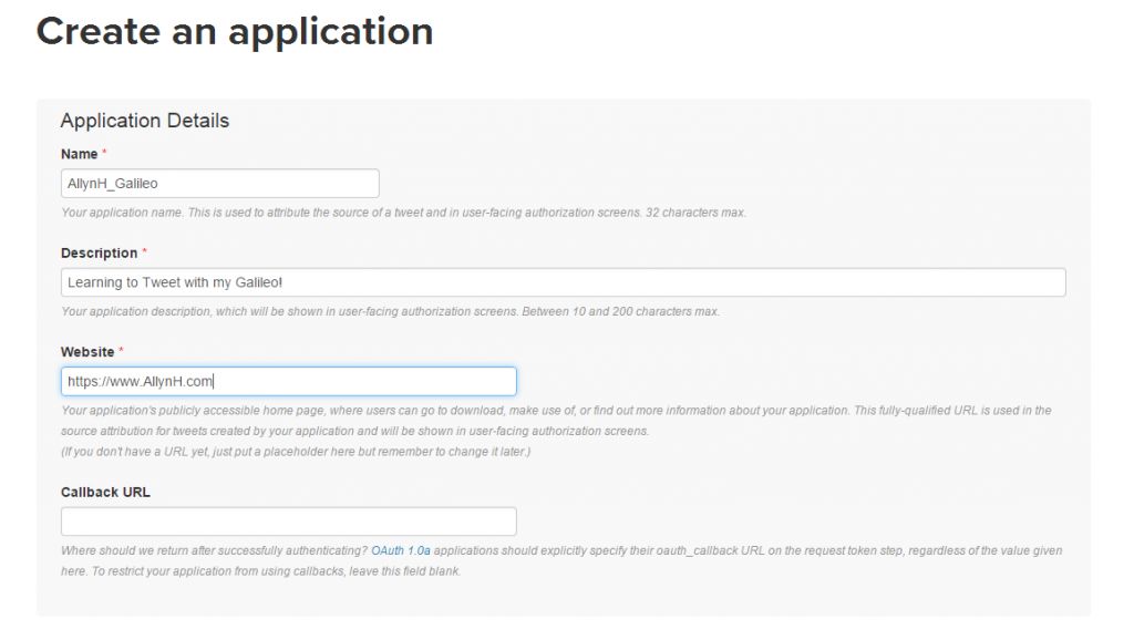
To create a Twitter App, you’ll need to sign up to Twitter and register the account as an application. This is important as you’ll need to verify this App with Twitter every time you use it. The verification method Twitter uses is called OAuth 2.0 to verify your App, this means you’ll never have to supply your password to 3rd party App developers but it does make it a little harder to verify your App – the good news is, Twython and other API’s handle all the OAuth pain, all you need to do is register your App and save the information. Register your app here: https://apps.twitter.com/ Click on “Create New App” and enter your information.

Let the fun begin!

Creating an App.


Changing App permissions:

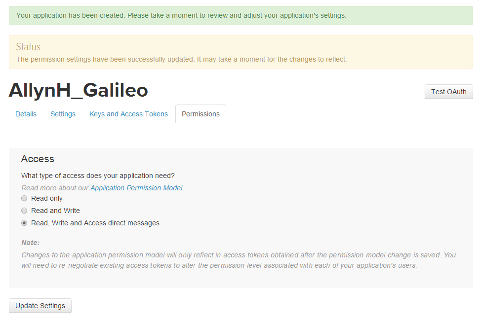
As this is your App and you’ll want to be able to play around with it – you can chance the App permissions to allow you to read, write and access your direct messages. You can change these permissions at a later stage.

Change permissions.

Change permissions.

Authorize your account:

You need to create your access token and access token secret before you use your App. Click on the “Keys and access tokens” tab. Click on the “Create my access token” button.

Generate your secret token.

Generate your secret token.

You should now have all 4 pieces of required information:

  1. Consumer Key (API key).
  2. Consumer Secret (API Secret).
  3. Access Token
  4. Access Token Secret.

Now it’s time to write some Python!

Writing the Python:

Creating a Python file:

On your Raspberry Pi or Galileo, create a file called “Tweet.py” using the following command:

# nano Tweet.py

Now paste in the Python code:

Twitter Authorization:

In order to send  a Tweet, you’ll need to send Twitter your OAuth information. This process is handled by the Twython package. Here we are creating 4 string objects and a Twython object called “twitter”. When we create the Twython object we are passing the 4 strings to it an arguments. These are the access keys you generated in the previous section.

CONSUMER_KEY = '<YOUR CONSUMER_KEY>'
CONSUMER_SECRET = '<YOUR CONSUMER_SECRET>'
ACCESS_KEY = '<YOUR ACCESS_KEY>'
ACCESS_SECRET = '<YOUR ACCESS_SECRET>'
twitter = Twython(CONSUMER_KEY,CONSUMER_SECRET,ACCESS_KEY,ACCESS_SECRET)

Reading in a command line argument:

To make the code a bit more flexible, we can pass the text we want to Tweet into the Python script as a command line argument. This is done by using the system “argv” parameter. In our case – we only want to take the first 140 characters of this text, as this is the character limit set by Twitter for each Tweet. We do that by using the command:

sys.argv[1][:140]

Executing the code:

You can execute the code from the command line like so:

# python Tweet.py "Hello world."

Here’s what that looks like on the Galileo:

First Tweet!

Hello World!

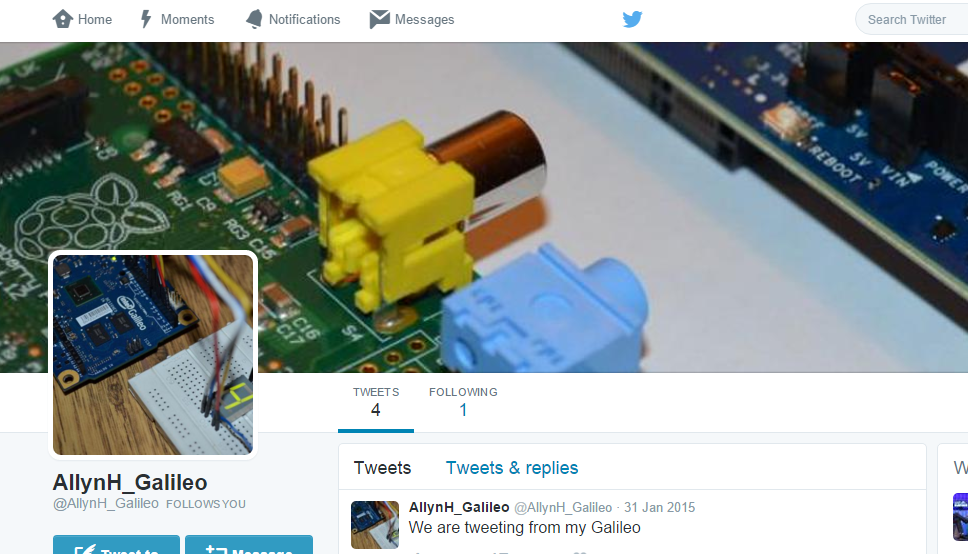
Then check your Twitter Bot!

Installing Debian on the Intel Galileo

Some of the guys in the Intel communities forum have done a great job of porting the Debian Linux distribution to the Intel Galileo. If you’re not familiar with the Debian, it is an open source operating system used on Linux systems. This is great news for the Galileo as it makes it very easy to port any Raspberry Pi based projects directly to the Galileo!

Debian was ported to the Galileo by StuartAnderson, who posted on the Intel Communities page.

You can download the Linux image from here!

What you’ll need:

  1. Galileo.
  2. SD card.
  3. Serial cable.

Downloading the Galileo Debian disk image:

You can find the Galileo Debian image here. Click on the “SD card image” file. This will take some time as the file is 900MB. While the disk image is downloading, we can prepare the SD card.

Formatting your SD Card:

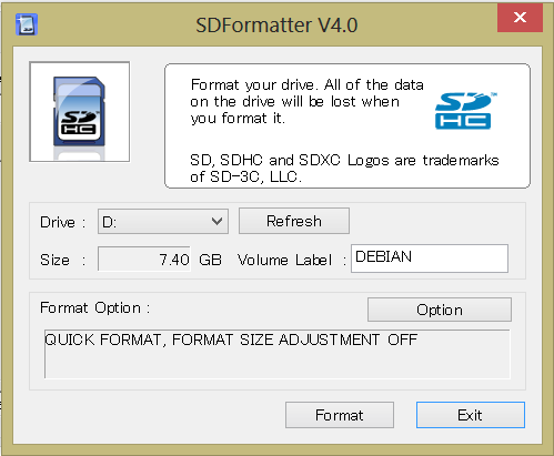
If your SD card has been used to write a Linux image before (used for a Raspberry Pi or Galileo Little Linux image), Windows can have trouble formatting the SD card. This is because Windows can only see the FAT32 partition and won’t see the much bigger Linux partition.

For this reason I used the SDformatter program from the SD Association, you can find it here (Click on Windows or Mac on the left).

You can see from the picture, I’m using an 8GB SD card (7.4GB shown but it’s 8GB, it’s normal for SD cards to be about 10% smaller than the advertised disk size), in my case Windows format only saw 56MB of the disk and ignored the remaining 7.35GB! However with the SD Formater program the full 7.4GB can be seen and will be formatted. Click on the Format button to start the process.

...

Using Rawrite32 to write the Galileo Debian disk image.

Writing the Debian Image to an SD card:

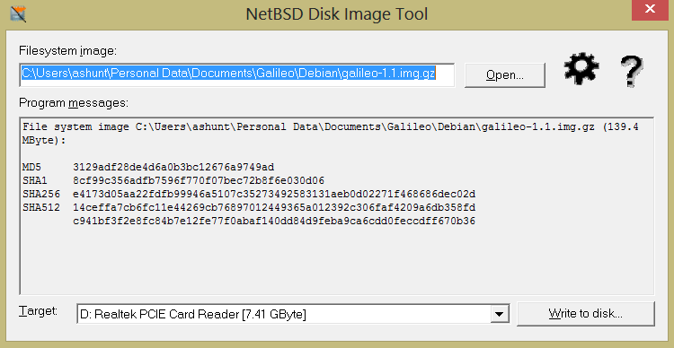
To write the Linux Debian image to the SD card you’ll need to download a disk image tool, as recommended by the original creators, I used the Rawrite32 Disk Image Tool software, found here.

After you’ve downloaded the Debian image, open Rawrite32 and select the Debian image to write.

Whoop - Debian!!!

Writing the Galileo Debian image.

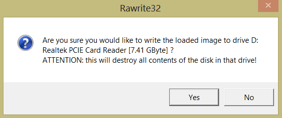
You’ll see a pretty scary warning like this, but as long as you’re sure there’s no important data on the SD card that you need, go ahead and click “Yes”!

Alt text for this picture.

Click OK to start writing the Disk Image.

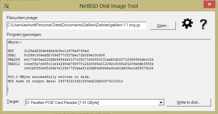
Once the Disk Image tool has finished writing – you’ll see something like this:

...

Finished writing the image.

You can see from the image above, the image file takes up 900MB, less than 1GB of my 7.4GB SD card. This means that the remaining 6.5GB of space on the SD card will not be available to me when I try to the Linux image. In order to make the remaining 6.5GB of space available, we need to grow the size of our partition on the SD card.

Now that we have a Debian Linux system available – this can be done from the Galileo itself!

Expanding the filesystem:

To expand the filesystem, first we need to expand the partition, then expand the file system to fill that partition.

When formatting the SD card, we could see that the 8GB SD card had a size of 7.4GB, so I’m going to expand my partition to 7.4GB just to be on the safe side.

Disk size before partitioning:

Not enough room!

Before resizing the filesystem.

Expanding the partition:

To resize the partition, we are going to use a program called Parted. This can be used to create, resize, move and destroy disk partitions. The first command used is the resizepart command.

# parted /dev/mmcblk0 resizepart 2

Select “y” to continue and then enter the size of the partition you want to create, here’s where I entered the 7.4GB (which works out as 7400MB).

# parted /dev/mmcblk0 resizepart 2

# parted /dev/mmcblk0 resizepart 2

You’ll need to reboot here!

# reboot

Expanding the filesystem:

When the partition has been resized we create a journal inode.

# tune2fs -j /dev/mmcblk0p2

# tune2fs -j /dev/mmcblk0p2

You’ll need to reboot here!

# reboot

When the reboot has finished, finish by expanding the filesystem to the partition size.

# resize2fs /dev/mmcblk0p2

# resize2fs /dev/mmcblk0p2

The resize2fs will expand the filesystem to fill the partition, this will take about 10 minutes but when it’s finished you should see a message like this, above.

Disk size after expanding the filesystem:

Loads of room!

Disk size after expanding the partition.

From the above image you can see, we’ve grown the filesystem to fill the partition, so we now have a total disk size of 6.8GB, with 6GB available to play with!

Now that the filesystem is expanded, it’s a good idea to update the system.

apt-get update && apt-get dist-upgrade

The update and upgrade will take about 10 minutes, then you can have fun playing with your new Debian computer.

Creating a Web Server on the Galileo: Using the Arduino IDE.

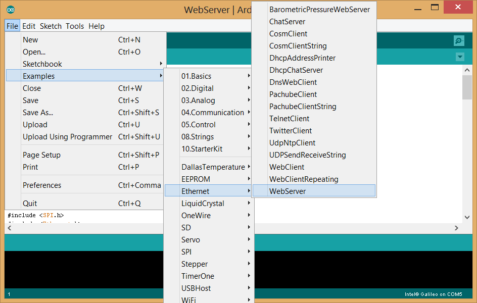
Creating a Web Server using the Arduino IDE example:

The Arduino IDE comes with a prebuilt Web Server example. If you’re not sure what a Web Server is, or what it’s used for – check out my blog post here -> Creating a Web Server on the Galileo

It's pretty sweet actually.

Arduino Example for creating a Web Server.

The above example comes with enough code to:

  • Create a Web Server on the given IP address.
  • Create a blank HTML page.
  • Read the analogue inputs and display their values on the HTML page.

How the Arduino Web Server works:

The Web Server uses the Arduino Ethernet library to answer any HTTP requests made to the Galileo. The Galileo already has an Ethernet connection on board and fully supports the Ethernet library.

Here’s how the library is explained on the Arduino website:

The library allows the Arduino device to connect to the internet. It can serve as either a server accepting incoming connections or a client making outgoing ones. The library supports up to four concurrent connection (incoming or outgoing or a combination).

The Arduino example does not conform to the full HTML page structure, and instead relies on printing text between the opening and closing HTML tags.
This is not the ideal solution for creating a fully functioning HTML page but it is a very quick and easy way to control your Galileo via a web browser. The example is pretty bare-bones, a HTML only website with no CSS styling or server side scripting functionality. Without any JavaScript or PHP, your page needs to be refreshed anytime the data changes.

Creating the Web Server in the Arduino IDE:

We start the Web Server by initialising the Ethernet class, to do this we need to call the Ethernet.begin() function and pass the required MAC and IP addresses to the function.

byte mac[] = { 0xDE, 0xAD, 0xBE, 0xEF, 0xFE, 0xED };
IPAddress ip(192,168,1,177);

void setup() {
//  Ethernet.begin(0xDE, 0xAD, 0xBE, 0xEF, 0xFE, 0xED, 192,168,1,177); 
    Ethernet.begin(mac, ip);
}

Once the Ethernet class has been initialised, we need to tell the server to listen for incoming connections on port 80, this is the default port for HTML requests, you can change this port number, which I will be doing in the Node.js example.

EthernetServer server(80);

void setup() {
  server.begin();
}

When the server is running and a client is available (connected via a web browser), the client.println() function is used to send data to all the connected devices. HTML can be printed directly using the client.println() function.

void loop() {
  client.println("<title> Allyns webserver: </title>");
}

The above code can be used to build a fully functioning Web Server.

Note:

At the time of writing there is a bug in the Arduino Ethernet library, which is discussed and a fix is suggested here.

Creating a Web Server on the Galileo

What is a Web Server?

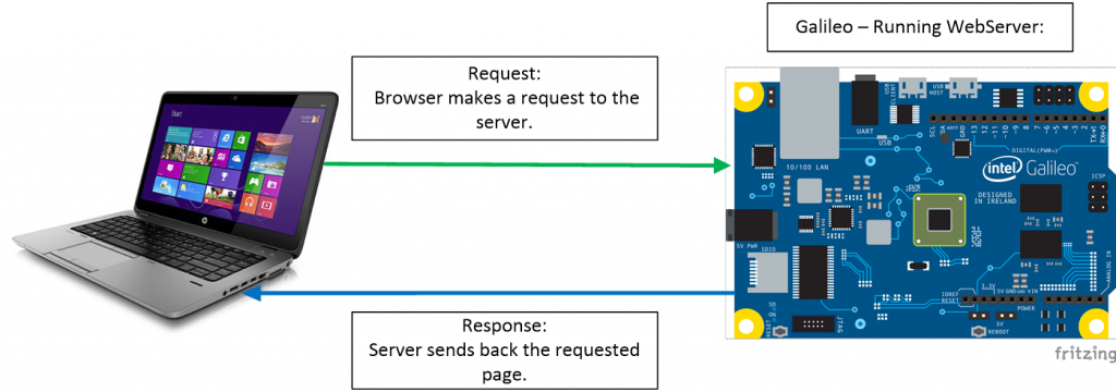
The Galileo, acting as a Web Server, can host a web page, this web page can be reached by opening a web browser and navigating to the IP address of the Galileo.
The Galileo will respond with the HTML you’ve created.

Galileo hosting a Web Server.

Galileo hosting a Web Server.

What is the Web Server used for?

The hosted web page acts as a user interface to the Galileo, this allows you to:

  • Control the GPIO pins, via a web interface.
  • Display the values of GPIO pins on your web page.
  • Send system commands to the operating system, via a web interface.

For more information on what a Web Server is, here are some useful links:

What is a Web Server – How Stuff Works.
Creating a Web Server with Arduino

How do we make a Web Server?

There are several ways to create a Web Server, the main 3 methods are:

Click on the links above to see how I’ve used these methods to create a Web Server.

Each of the above has their own benefits and drawbacks, for example, using the Arduino IDE example is the least flexible Web Server methodology – however it provides the best (in my opinion) interface to control the GPIO’s.

Time-lapse photography using the Galileo and IR remote control.

I decided to try my hand at some time-lapse photography using the IR remote control I made for the Galileo.
I set the code to take a picture every 20 seconds and left the camera alone to do its thing…

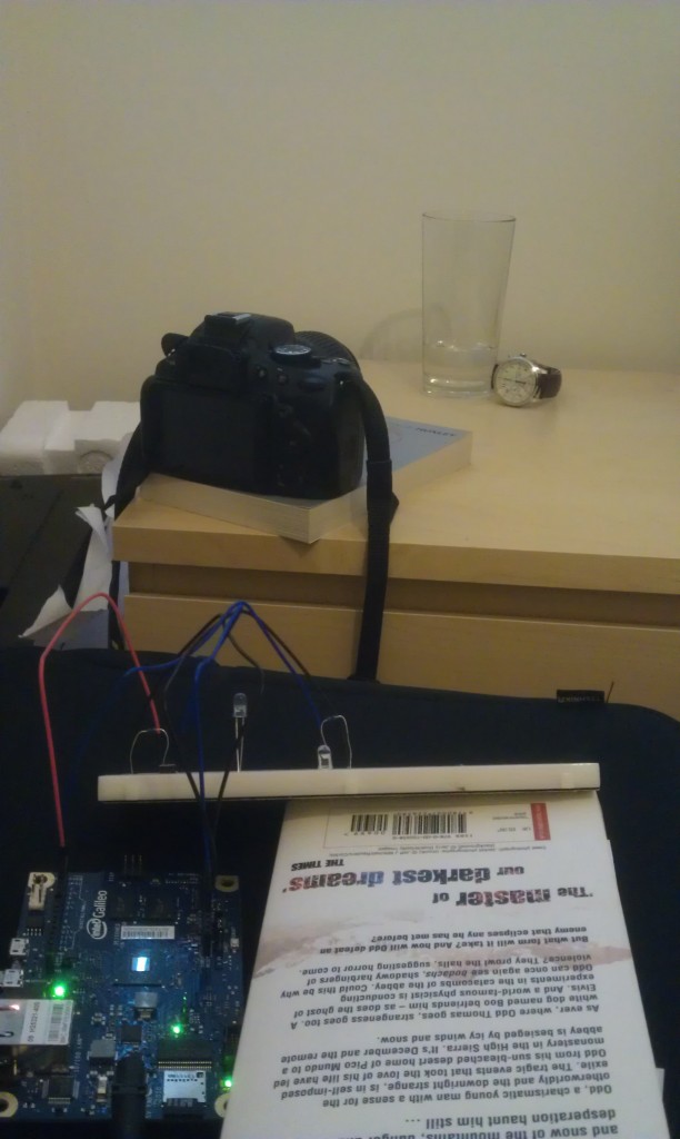
Here is a picture of the Galileo setup:

The book is - Brother Odd by Dean Koontz.

The IR remote is built on a breadboard and being propped up to point it at the camera.

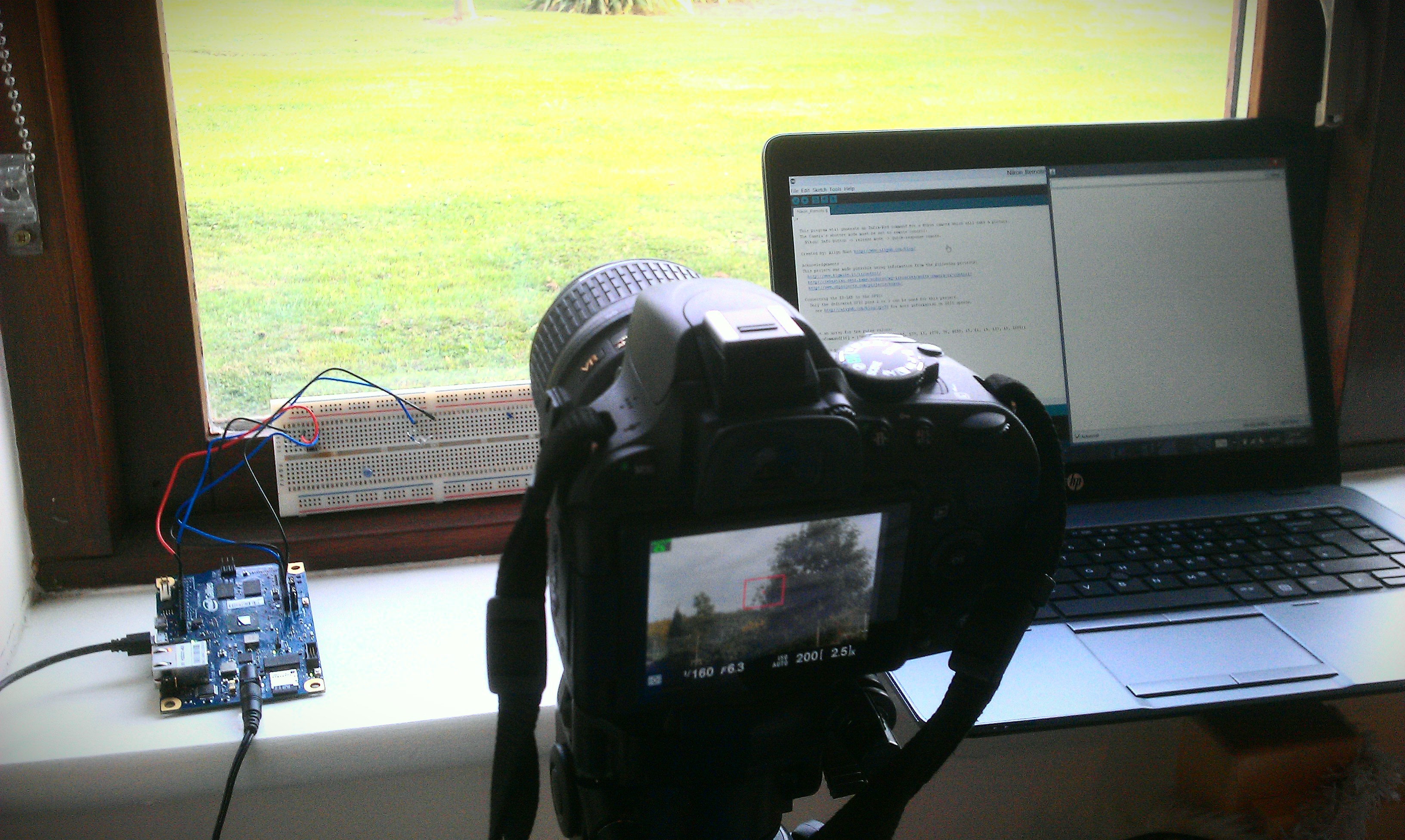
Here you can see the picture count being displayed on my laptop:

Brave New World - Aldous Huxley.

Laptop displaying current number of pictures taken.

Here’s the result:

Time-lapse photography, made using Galileo and IR remote control. from Allyn H on Vimeo.

Making an IR remote control for a Nikon camera:

Introduction:

I started this project as a bit fun, when I first bought my Galileo board. As this was my first Arduino project, I decided to try downloading an already completed project and get it working on my own board. I soon realised this wouldn’t be as easy as I thought…
As the Intel Galileo is actually a Linux computer emulating the Arduino IDE, the GPIO speeds are a lot slower on the Galileo when compared to a dedicated microcontroller. This proved to be a big problem for me, as it meant I couldn’t just run any of the timing or frequency dependant Arduino projects directly on the Galileo.

With this in mind, I decided to build the Infra-Red remote control for my Nikon SLR camera. As the Arduino libraries would not work for the Galileo, I decided to build my own.

How the command signal works:

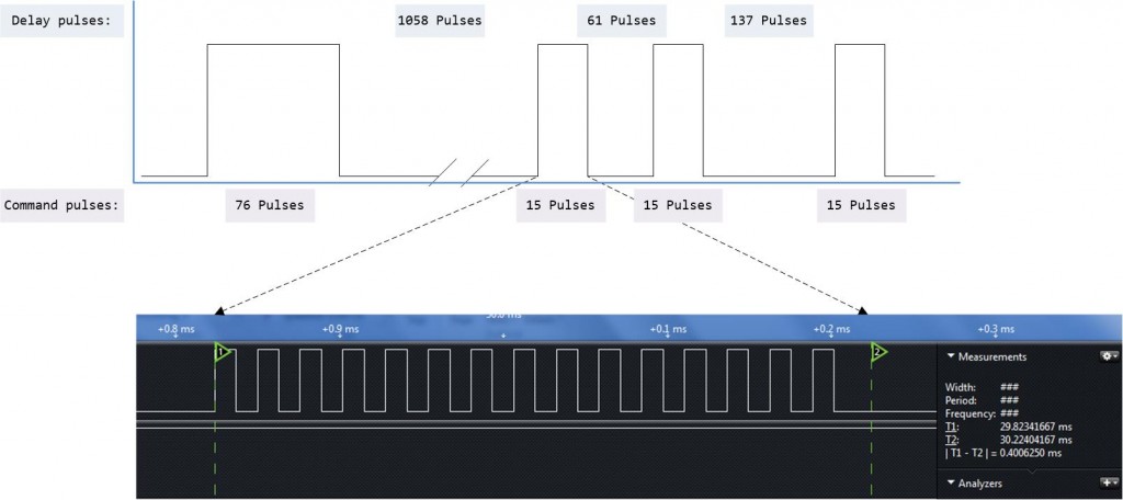
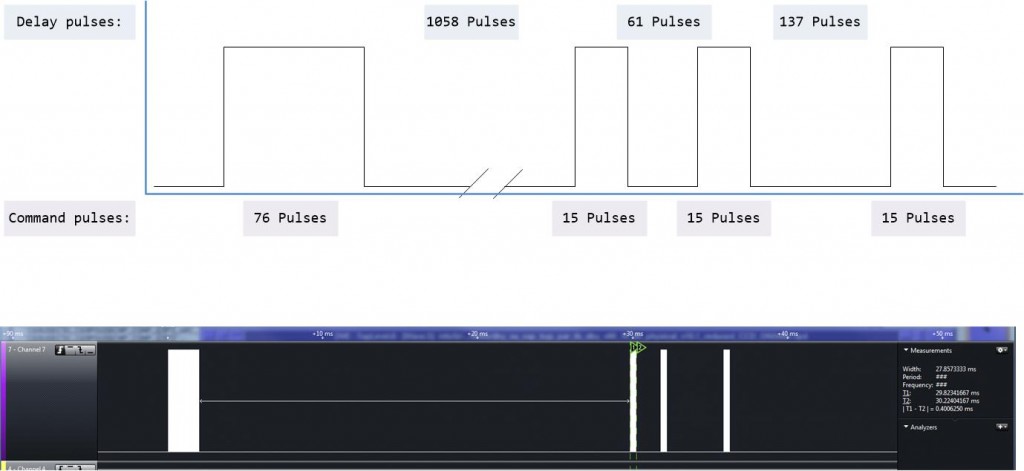
The command signal is transmitted on a 38.4KHz carrier wave, the command signal is sent in a binary format.
This means, when sending a binary “1”, the LED is turned on and off at a frequency of 38400 times a second for a given time period of 400uS. When transmitting a “0”, the LED remains off for 400uS.
Luckily for me the command signal for the Nikon camera has already been decoded and published, the details can be found here: http://www.sbprojects.com/projects/nikon/

So, from observing the diagram on the SB Projects page, we can convert each binary value of the command signal into a series of pulses generated on the carrier frequency. The pulses can be turned on or off to generate the binary values.

Cool stuff, eh?

Creating a binary “1” and piecing together the command signal.


Parts list:

  • Intel Galileo.
  • IR LED – I broke open an old remote control and took the LED from here.
  • Resistor – 220Ω.
  • Breadboard – for building a prototype design.
  • Nikon Camera – you know, to use the remote control on…

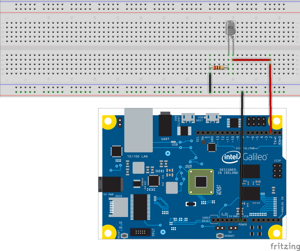
Schematic:

It's pretty basic, honestly...

Schematic diagram for the circuit.

Salvaging an IR LED from an old remote:

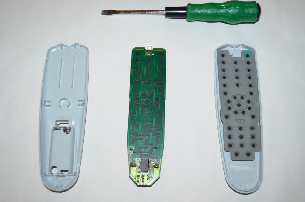
I had been looking to buy an IR LED but as they’re so cheap, I couldn’t find anywhere that would ship one to me unless I bought about €40 worth of items, so my dad donated his old TV remote, which I broke open and removed the IR LED.

Time to open it up and remove the LED:

inside out.

Work in progress.

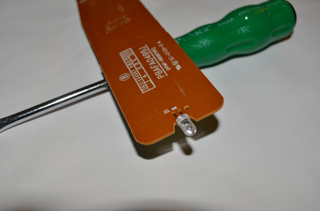
I used a wire snips to cut off the IR LED:

D'oh!

Here’s a close up of the IR LED, just in case you’ve read this far and still don’t know what I’m taking about (highly possible).

Creating the 38.4KHz clock pulses:

In order to generate the command pulse, we need to be able to create a clock frequency of 38.4KHz and turn this off and on to create the binary values. I’ve already created a post on how to create a clock pulse using the Galileo, you can view it here.

For this project I am using the method shown in example 1, which is plenty fast for what we need.

The code from example 1 outputs a 444KHz frequency (I’ve measured this as 444KHz, it should be 477KHz, which is why some of the maths may not add up), which is way too fast, so we’ll need to add in a delay to slow that down, in this case the delay is created with an “for statement”. We use a delay value of 12 as this translates to 38.4KHz, so in order to generate the required frequency – we turn on the LED and count for 12 clock periods, then turn off the LED and count for another 12 clock periods.

void pulseLoop(int pulses, int SHINE)
{
  // Integers for loops:
  int i;
  int n;
  // delayValue is used to delay the clock from 460KHz to 38.4KHz:
  int delayValue = 12;

  register int x = 0;

  // Loop to control the number of pulses created
  // Number is multiplied by 2 to create both the low and high period of the pulse:
  for(n=0; n<(pulses*2); n++)
  {
    // Loop to delay the digitalWrite to 38.4KHz:
    for(i=0; i<delayValue; i++)
      {
        // SHINE only activated the IR LED when we are supposed to pulse, deactivates for the delay:
        digitalWrite(2, (x & SHINE));
      }
    x =!x;
 }
}

Here’s how that code looks on a Logic Analyser:

Quality picture, eh?

38.4KHz clock frequency created using the GPIO example 1.

Using the code above, we can call the function pulseLoop and pass the number of required pulses and the LED state as an argument, for example we could just type in:

  // First Pulse:
  pulseLoop(76, 1);
  pulseLoop(1058, 0);
  pulseLoop(15, 1);
  pulseLoop(61, 0);
  pulseLoop(15, 1);
  pulseLoop(137, 0);
  pulseLoop(15, 1);
  // Wait for 2nd pulse
  pulseLoop(1078, 0);
  // Second Pulse:
  pulseLoop(76, 1);
  pulseLoop(1058, 0);
  pulseLoop(15, 1);
  pulseLoop(61, 0);
  pulseLoop(15, 1);
  pulseLoop(137, 0);
  pulseLoop(15, 1);

Creating the full command:

The code above works – however it’s a bit too messy and just not cool really..
So lets put all of our pulse values into an array and create a new function which will use that array to build the command.

// Create an array for the pulse values:
int nikonCommand[16] = {76, 1058, 15, 61, 15, 137, 15, 1078, 76, 1058, 15, 61, 15, 137, 15, 1078};

void takePicNikon()
{
for(int x=0; x<sizeof(nikonCommand)/sizeof(int); x++)
  {
    int y = x + 1;
      pulseLoop(nikonCommand[x], (y%2));
  }
}

The line “pulseLoop(nikonCommand[x], (y%2));” uses the C language modulus operator to tells us if the index number is even, if it is we pass a “1” into the pulseLoop function, this will switch on the LED for each item in the array.

Full command:

Using the above code, it was possible to replicate the command required for the Nikon camera, here is a

Coooollll...

The full command pulse, with the Logic Analyser data.


It’s Working!!!

This is also Horstachio’s big screen debut…

Galileo – IR Remote for Nikon Camera.. from Allyn H on Vimeo.

Grab the code here:

Feel free to use my code, make something yourself. It should be very easy to port this to any other make camera.

Please let me know if you plan on using this in any projects 🙂

Link to my code on GitHub.

Intel Galileo – Getting to grips with GPIO speeds:

Using the fastGpioDigitalWriteDestructive command to write to the GPIO's.

Using the fastGpioDigitalWriteDestructive command to write to the GPIO’s.

As part of my latest project, I’ve been trying to come to terms with how the GPIO’s (General Purpose Input / Output) on the  Galileo work, there are several ways to program the Galileo I/O’s, mainly: GPO, SPI or ADC.

As the Galileo is running Linux and emulating the Arduino IDE, the GPIO’s run a lot slower than expected, as the chip copes with this overhead.

The GPIO’s on the Galileo are routed through the Cypress CY8C9540A chip, which drastically slows down the performance of these pins, however, not all of the GPIO pins are routed through the PWM.

While reading up on this, I found the below post by “deckard026354” on the Intel communities site, which states the Galileo has 2 dedicated IO’s  with “significant data rates”.

https://communities.intel.com/message/207904#207904

I managed to get my hands on a Saleae Logic Analyser, which I used to measure the speeds of the GPIO.

I created a basic sketch on the Arduino IDE and measured the frequency at the Galileo outputs.

Default speed – 226Hz:

int led = 2;

void setup() {                
  pinMode(led, OUTPUT);     
}

void loop() {
  digitalWrite(led, HIGH);
  digitalWrite(led, LOW);
}

Output:

As expected, the wave form reads 226Hz, pretty slow though – so lets see what we can do about that.

Don't hover over me, it's creepy...

Default 226Hz


Example-1 – outputs 477kHz waveform on IO2:

void setup() {
  // put your setup code here, to run once:
  pinMode(2, OUTPUT_FAST);
}

void loop() {
  // put your main code here, to run repeatedly: 
  digitalWrite(2, HIGH);
  digitalWrite(2, LOW);  
}

Output:

The output measures 444KHz, not too shabby. Although I seem to me missing 33Hz…  I’ve measured this a few times and am pretty sure it’s accurate. So it could possibly be down to the overhead from the Galileo emulating the Arduino IDE.

Using the OUTPUT_FAST pinMode definition.

Using the OUTPUT_FAST pinMode definition.

Example-2 – outputs 683kHz waveform on IO3:

void setup(){
    pinMode(2, OUTPUT_FAST);
}

void loop()
{
    register int x = 0;
    while(1){
        fastGpioDigitalWrite(GPIO_FAST_IO2, x);
        x =!x;
    }

}
Using the fastGpioDigitalWrite command to write to the GPIO.

Using the fastGpioDigitalWrite command to write to the GPIO.

Output – 705KHz: 

The pulses generated seemed to alternate between 667KHz and 705KHz, I’m not sure if this is an inaccuracy with the Galileo or the Saleae, although this does average at 686KHz, so it looks to be an issue with the measurement.

Controlling the GPIO's with fastGpioDigitalWrite.

Controlling the GPIO’s with fastGpioDigitalWrite.

Example-3 – outputs 2.93MHz waveform on IO3:

uint32_t latchValue;

void setup(){
    pinMode(3, OUTPUT_FAST);
    latchValue = fastGpioDigitalLatch();
}

void loop()
{
    while(1){
        fastGpioDigitalWriteDestructive(latchValue);
       latchValue ^= GPIO_FAST_IO3;
    }

}

Output:

Nice! 3MHz from a GPIO,

Although I’m a bit worried about the function name “fastGpioDigitalWriteDestructive“, so I’d like to know a bit more about this before using it in a dedicated sketch.

Using the fastGpioDigitalWriteDestructive command to write to the GPIO's.

Using the fastGpioDigitalWriteDestructive command to write to the GPIO’s.


Example-4 – outputs 2.93MHz waveform on both IO2 and IO3:

uint32_t latchValue;

void setup(){
    pinMode(2, OUTPUT_FAST);
    pinMode(3, OUTPUT_FAST);
    latchValue = fastGpioDigitalLatch(); // latch initial state
}

void loop()
{
    while(1){
        fastGpioDigitalWriteDestructive(latchValue);
        if(latchValue & GPIO_FAST_IO3){
            latchValue |= GPIO_FAST_IO2;
            latchValue &= ~ GPIO_FAST_IO3;
        }else{
            latchValue |= GPIO_FAST_IO3;
            latchValue &= GPIO_FAST_IO2;
        }
    }
}

Output:

I didn’t get this to work -_-

If I get a chance, I’ll go through the code again at a later stage and debug…


So there you go, depending on how you program IO2 or IO3, you can get:

  • 226Hz by using the default setup.
  • 477KHz by using pinMode(2, OUTPUT_FAST).
  • 683KHz by using fastGpioDigitalWrite(GPIO_FAST_IO3, x);
  • 2.93MHz by using fastGpioDigitalWriteDestructive – although I don’t like the sound of this command…

© 2024 Allyn H

Theme by Anders NorenUp ↑